United Kingdom

United Kingdom
Click on pictures for larger view, contact me at williams4x4@gmail.com

19 September 2012

Tailgate opening problem, update your rear view mirror and fuel hose replacement

Just to spike your intesrest, this new page will be updated very, very shortly (2 to 3 days)

This addition is somewhat a mix of two, first up to the dreaded tailgate not opening caused by either a failed opening button switch or actuator.

The procedure is very simple and ideal to do before a problem occurs which I can assure you.....its inevitable.

If this has happened to you and you cant open the tailgate you will need to get into the back by folding down the seats and climb in, no need to lift out the spare wheel cover as per other Internet remarks regarding this issue.

I'm sure the below pics will be clear to all, do it now and test before it happens to you.


Above is simple enough, once you have measured make a mark with a marking pen (Black dot)
Measure from edge as per picture, make a mark on tape, measure from (opps I'll update this 2mrw, forgot if its top or bottom) edge of plastic and you have your punch hole you are going to make with the screw driver, time needed.....about 2 minutes, 10 if you put the kettle on

Basically you need a marker, some masking tape if you like and a thin flat bladed screw driver, the only part you need is a small plug of sorts...read on


Do not line up with lower securing board screwy thing, its not that simple and that would be too easy..


Once you have made the mark simply punch through gently, now test with the screw driver straight in by merely going sideways to the left, not up and down, the screw driver is acting like a lever, the first click opens the upper tail gate and the next the lower section, screw driver will go on quite a angle but you'll get the hang of it.


The plug part is to close up the hole and ready for when you really need it, also serves as reminder that you have a solution at hand when it does happen one day


All neat and to the point, you could possibly really have a boring debut one day with another Rangie lover and point them to this blog about how important that little hole really is, I rank this simple but important mod the 1st to do on your list.


Rear view mirror upgrade, this is for P38s from 1994 to 1998, pre Thor engine setup

A quick overview.

The introduction of the...wait for it... the "Electrochromic interior mirror" or shall I merely say electronic rear view mirror is a nice addition to the the P38, however the early models are now problematic and to replace them cost a arm and a few other body parts but it don't need to as a Disco II electronic mirror works.

The only minor snag you will notice is the mirror sits slightly lower, but that can be moved up on your next windscreen replacement, the other is the wiring as the colours are not the same and so a little logic is needed to perform this fantastic upgrade, I say fantastic as the later mirrors are so much better.


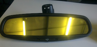
Your old crummy mirror, dull and yellow
Below the DII, has a intersting vague blue tint to it


The replacement Disco II mirror, if you are lucky you might be able to pick up one with a built in compass, mine has the compass and is not that common so hunt one down if its really that important.
Most D II electronic mirrors don't have the compass bit. 

What you need to do is to try and get the plug end off the donor vehicle, I was not so lucky and had to struggle abit to solder the wires together


You will need to remove the securing metal tab from your old mirror and install it onto the replacement mirror
If you cant get the plug end from the donor vehicle you will need to cut off the mirror side part from your old mirror


This is the DII mirror plug, alot different......really try and get the other plug side


Don't mess here as this is the compass bit, mess this up ad it wont work


Installed and works well, not pictured is a tidy up tube added to exposed wires in top of pic

The three wires on the P38 1994 to 98 is as follows.
White = Power supply +
Brown = Negative (Earth)
Grey = signal from gearbox in reverse (supplies a negative)

I'll add the D II mirror wire colours and functions 2mrw

++++++VERY IMPORTANT++++++
The DII gearbox reverse signal is positive, do not connect yet as I'm scouting for a micro 12 volt relay to convert the signal to positive, the P38 1994 to 98 is negative and needs to be converted to negative for the mirror to come out of dim mode when reversing at night, update to follow very shortly showing how to do this (very simple)

FUEL HOSES (1994 on - GEMs) Critical

I advise anyone with a GEMs setup to replace as an emergency to do, you must replace your fuel hoses now.

I know now of 7 P38s that have gone up in flames, one was caught in the nick of time and minor damaged occurred..
The Rest....total burn outs

How to do it
But most importantly use High quality hosing and clamps, trust me your spare shop will try and sell you cheap fuel hosing and clamps, go to a hydraulics company and get the best


First remove the plastic bracket retainer to allow for easy access of fuel hose crimp cutting


Here we used a mini hand hacksaw to cut through the crimp section, do a Little at a time to ensure you don't cut into the steel hose section


The crimp section is now ready to be prided open using a large bladed screw driver will do it easily, you will need to tear the crimp section that you wernt able to cut, easily done with a pair of pliers.


really simple and its off, now you can remove the pipe and replace it
When doing the pipe that is connected to the fuel rail using a pipe fitting it is best to remove and place in a vice to cut the crimp section of the fitting. 


Now a new quality fuel hose can be attached

New piping and clamps attached, give your self a good half hour to do the job
DO NOT SKIMP ON QUALITY OF PIPE, there's loads of rubbish out there


17 September 2012

Water leaking into vehicle (Wet carpet) RDH - Further additions to follow very shortly

Have you washed your Rangie or its been raining cats and dogs and now you have wet carpets, well the fix is relatively straight forward but requires attention to detail.

My personal vehicle always had this problem but I was not able to trace as every time I wanted too take it further the vehicle effected parts had dried up, after moving from Johannesburg or Joburg as our foreign visitors will know it down to the sunshine coastal city of Durban where it can rain a lot and it does…… I one day pounced on the vehicle and solved the riddle.
Without further delay here are my findings and remedy, since the fix there has not been one drop of water or misting up of the windscreen during any type of rain drives recently.
First up you need to remove both wiper blades

Remove Windscreen side finishers – trim

Remove windscreen lower finisher – trim
Remove plenum plastics that allow air through the grills and into vehicle (vent intake)

By now you would have gone through the pictures, important to note that a quality silicon sealant must be used in the sealing up of the effected parts.

Consult someone who knows sealants and not your spares guys, they will sell and miss inform you just to sell a product, very few parts guys really know anything technical, the rest are know jack shit.

Do Not be over whelmed by the many picutres below, once you start its not that bad, for a quality repair put aside 5 to 6 hours, if you have someone to help you it goes alot quicker, we charge 4 to 5 hours for this repair, depending if there are no major issues like re-meshing vent intake

Please note the beow pics are for Right hand drive vehicles but doubt its much different for LHD


Remove trim from under dash, as circled these are wet patches and is a sure sign that water is leaking in

Wiper arms and lower trim needs to be removed

Windscreen side finisher - trim to be removed, there are screws that hold this in place and are hidden under the rubber flap of the trim


Once you have all the vent intake trim (Plenum) removed you can start by sealing this section.
Not in the picture there is a rubber blank that goes in here, apply sealant around edge and insert rubber blank


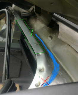
Its all wet and it should not be (Red cross) right circled indicates one of the problems where water seeps past , left circle shows where water has been dripping on to wiper arm mechanism, this should be dry.


By now you would have inspected and cleaned all the removed parts, this is the steel plate that covers the pollen filter cavity, the circled section is where the water is making its way past the foam seal, in effect this is a bad design that is now only starting to pop up, when it was new all was ok....so we thought.
As the water works past the foam it absorbs the water and allows it to run along the entire length of the foam seal (blue), this was identified by using a flex mirror to poke under this panel prior to removal, this is only one of the problem areas.


All three circles is where the water works past, the right circles is the area that needs serious attention and is detailed in the below picture, the middle is where one of the bolt's goes through that retains the plate in position, the left circle is also a major leak area, all three need proper cleaning and sealing up.


Sealant needs to be applied with great detail in this area, work the sealant as far up under or up to the windscreen glass edge and along the panel edge, note that the panel was re-installed after cleaning and  sealant was applied to the foam seal, DO NOT apply sealant to the foam seal and then mount the panel, if you do it will promote rust in no time


This part is abit tricky but not dangerous, the plastic piece here is for when the windscreen is replaced and aids the installer to mount the windscreen correctly, this part however needs to be lifted up to allow abit of sealant to be applied underneath, just lift it up a little, one of two tags may give but that's ok as its going to be sealed up anyway, do not try and remove it.   The blue indicates how the water works past in this critical and main area of concern


Water works its way around and under this plastic screw insert, you need to clean and properly seal around this section.   Water here drips past and onto arm (circled) and then drips onto pollen filter where it saturates the filters and pours through the fans into the vehicle.


No doubt you know where this is, well its another area that needs attention


And this is what you need to do, apply and work in the sealant well.


Assemble the trim panel while the silicon is still not cured as this will allow for better sealing all round, note I even applied sealant into the screw hole.


Now you can see why you need to seal very well in the previous pictures, this plastic finisher panel was removed and as you can see there is water around (not through) this screw insert, the insert itself does not leak but will do if you use screws which are too long


At the start I assume you would have removed the pollen filter, if so you can give it a wash or replace.
To wash simply soak it in a cold bucket of water with abit of dish washing liquid, let soak for awhile and rinse well, leave in the sun to dry while you carry out the sealing up repair.
It is important to make sure that the pollen filters are installed, failure to do so will allow dust to settle on the fine fins of the AC system and block it up, this in turn will make the AC compressor over work and cause premature failure due to accelerated wear (High duty cycles).


Three years later after installing the mesh instead of the foam on the vent intake it still looks pretty good, note the absence of leaves, twigs etc, a good rinse out is all it required and the water flowed through the drain channels quickly, mesh repair is detailed on this blog in depth


Water water everywhere


To spike you all a cure has been found for the really bad water entry into spare wheel compartment and here is one of the pictures detailing one of five problem areas, the rest is to follow very shortly


This is a problem on ALL p38s, from 1994 to 2002
The green indicates ok as this is not the problem area.
Blue is how the water runs
Red is where one of the problems start.


13 January 2012

Heater pipe looping due to leaks

Quite a number of overheated engines we have carried out repairs on all have come in with the heater pipes removed and the hoses looped, though this is correct the one important problem we have found with this is the incorrect looping of hoses has either been done incorrectly or the hose has been kinked over so much that it hardly allows for the heated coolant to flow to the thermostat for correct temperature regulation of the engine, in effect causing the engine to overheat.


It is very important that if you carry out the heater core bypass method that there is full flow of the coolant.

As pictured below you can see that the pipes have been arranged so there is full flow of the coolant

Another mistake we have noted is the incorrect connecting of these pipes, remember that coolant also flows back out the reservoir bottle too, if the pipe coming from the engine is opposing the flow from the reservoir due incorrect bypassing then this action will cause a mild overheat situation at irregular intervals.

The below picture is based on the GEMs engine.
On the Thor (Bosch injection) looping the heater pipes involves a bit more but the effect of making sure the flow of coolant is the same as the GEMs, get this wrong and you are 100% guaranteed to blow your engine

Rover V8 Rockers (corrected) and bad timing chain (Not BMW or Ford powered LR's)

*****UPDATE*****
16/04/2014
Pats manufacturer /suppliers Bearmach sent a e-mailed and assured me that their new rockers are up to the correct OEM specifications.
I see no reason not to purchase the Bearmach rockers and I would like to thank them for letting us know so we could let you know, they have kindly offered us a full set for testing and will contact them ASAP so we can do a test to determine this issue, just in time as four rebuilds are in progress, one needs a full set of new rockers due to extreme high mileage

A big thumbs up to Bearmach for the feedback, rare in todays world of parts manufacturers/suppliers.

As a rule I hate mentioning a part brand but in this case for obvious reasons I’m going to for the simple fact to try save many owners the misery of asking why their motors are burning engine oil or wearing out internal parts sooner than they should due to loss of oil pressure
You would think a simple part like a rocker would be of no concern, well that’s not the case.
Pictures taken whilst engine was running


Note in the pictures the high flow of oil with Bearmach rockers (first and above pic) vs the originals (middle pic), this excessive oil is flooding the valve stem seals, great for lubricating but there’s another sinister knock off effect to be had when this happens.

Please note that we did pick up the same issue with Britpart rockers but to date we have not been contacted regarding their issue.

Jeremy Clarkson is a motor journalist, and a good one at that too, we're a repair shop and our job is to source high quality parts for your vehicle......so whats this all about you ask...... you see Mr Clarkson gets a car to test and his job is to evaluate it in every way possible within a certain category, lets be honest a Rolls Royce is the best car out there vs a Kia something or another with a few quick noddles attached to its tail pipe, whereas a Roller......well it's simply just the ultimate in motoring pleasure.

Let's get back to the issue at hand...
So while the issue now seems to be resolved with Bearmach this info won't be deleted and is ideal as a case study for future reference.
So...
I may have mentioned the brand's and the cause was simple to see why, the machined groove across (there's two) is too deep which allowed for excessive oil to flow.

When the engine is up to operating temperature those valve stems get very hot, the oil that passes the valve stem seal is now a bit too much and so a carbon build up is going to occur on the stem, although not right away because you may have just had the heads off and all the valve stem seals were replaced

As pictured below note the oil flow is a lot less as these are original rockers


We carried out this investigation because we were not too happy with the oil pressure results and as they say a picture says it all, in this case there is no question where the oil pressure drop was going.

Always remember to get pressure you have to have a restriction to flow otherwise there is no pressure, when you have pressure you have lubrication.

On the Rover V8 the camshaft is the first to suffer when there is a pressure drop due to the hydraulic lifters positioning.

Timing chain update:

Rover V8 timing chain - affects ALL Rover V8s.
This latest update is not all model Land rovers but for all the classic, Defenders, P38's, Disco 1 & 2 fitted with the V8 motors.

After market timing chain as detailed in the pics below are a cause for concern, these chains are stretching so fast and so much more than the original it kind of defies belief, why, well for starters in today's manufacturing world I see no reason why a chain of this importance is being made to such low standards and hence why on every rebuild or repair job we do relating to anything near a chain we only go original.
One would have thought a chain of this low crap quality would have come out of a low level third world country, sadly it comes from the USA.
Now the weird part is the original chain which does look and is manufactured differently is still made in the USA.....but by whom.

See for yourself...

I have never seen a chain as bad as this before

Lets go real floppy shall we, will it jump a tooth, you bet it will.

Top chain is Original Land Rover
Bottom chain is aftermarket

Yellow oval circle - Solid chain links.
Red oval circle - Plate links, 2 by side and thinner.
Left red lines - Pins lined up.....ok so.
Right yellow lines - Pins no longer line up = stretched chain

This aftermarket chain was removed at around 10 000ks of installation
having recently rebuilt my very own V8 motor for my P38 the original chain was strecthed but quarter of what you see in the first picture and that was with 230 000 + km's
The replacement chain was so badly stretched you could feel when turning the front crank pulley.

On average the timing chain should be replaced at around 150 000k's, sometimes sooner depending on driving climate...ie more open road driving, chain will last longer vs town stop go all the time

I hope this persuades all the Rover V8 owners out there to demand or to use Genuine land Rover timing chains, if you cannot afford the original chain then why are you driving a V8 anyway ? 
A tank of fuel costs more than the part, ironically "some" people seem to not know any better...(bangs head on wall) that includes part suppliers too, wake up we dont want to buy your sub standard parts